


High-Reliability Wind Energy Welding Solutions
As the wind power industry moves toward larger-scale and offshore development, welding and cutting technologies face unprecedented challenges: tower heights exceeding 150 meters, single-unit capacities reaching 15 MW, and harsher offshore corrosion environments.
We focus on three critical application scenarios—tower section circumferential seam welding, nacelle base to flange welding, and precision plate cutting—providing end-to-end solutions to help our customers achieve zero-defect welding, millimeter-level cutting accuracy, and 18% reduction in total lifecycle cost.
01|Tower Section Circumferential Welding
— Securing the “Lifeline Weld” of a 100-Meter Steel Tower


Background and Industry Challenges
As tower heights rise from 80 to 160 meters, with individual sections exceeding 5 meters in diameter and up to 100 mm in wall thickness, traditional manual welding reveals serious shortcomings:
Fatigue Cracks: A 2.5 MW onshore turbine experienced tower cracking after 3 years due to incomplete penetration in the circumferential seam, causing direct losses over ¥6 million.
Low Efficiency: Manual welding of a 20-meter seam takes 6 hours—only one-quarter the efficiency of automated welding.
Quality Fluctuations: Weld reinforcement deviations of ±2 mm increase the risk of misalignment during tower assembly.

Technical Challenges
| Requirement | Specification |
| Structural Strength | Full penetration welds; tensile strength ≥ 540 MPa (matching Q355D base material) |
| Process Control | Continuous welding over 20 meters without arc interruption; interpass temperature strictly controlled between 100–150°C |
| Inspection Standard | 100% ultrasonic testing (UT) + magnetic particle testing (MT); compliant with EN 1090-2 |
Recommended Solution

MIG 501D Automatic Welding Torch:
● Water-cooled system, supports 500A / 60V continuous output (100% duty cycle)
● Compatible with Φ0.8–1.6 mm wire; deposition rate up to 12 kg/h
● Stable arc control; weld consistency > 98%, significantly improving first-pass UT acceptance rate

Wind Energy Solutions
Innotec provides more than just equipment. We serve as lifelong trainers and advisers who are dedicated to the success of your wind energy project and are there when you need us most. Contact an expert in your area today, and let’s talk about how to take your project to new heights.
02|Nacelle Flange Welding
— Solving the Fatigue Failure Challenge Under Dynamic Loads
Recommended Solution

AUTO MIG 501D (Main Welding)
● High current output for vertical/uphill welding positions
● High reliability for multi-pass welding
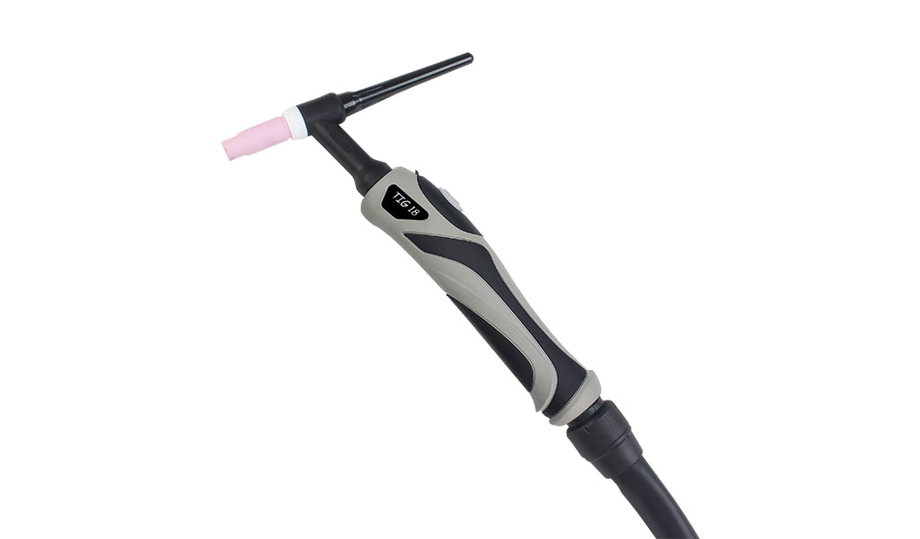
TIG 18 Water-Cooled Torch (Finishing):
● 100% DC: 320 A | 100% AC: 240 A
● Electrode Size: 0.5 – 4.0 mm
Advantages:
● Precise filler control for dissimilar steels and complex grooves
● Ideal for stress-concentrated area reinforcement and repair

Application Scenario and Failure Case
Nacelle flange joints must withstand cyclic loads (200–2000 kN) and high-frequency vibrations (20 Hz). A marine wind farm once reported fatigue cracks in flange welds after only 18 months of operation, causing a 12 mm displacement in the gearbox. Traditional processes face two main bottlenecks:
Excessive Deformation: Uneven heat input results in flange flatness deviations >1.5 mm/m
High Residual Stress: Poor overlap in manual multi-pass welds causes local stress peaks up to 350 MPa (80% of material yield strength)
Technical Challenges
| Requirement | Specification |
| Structural Strength | Full penetration welds; tensile strength ≥ 540 MPa (matching Q355D base material) |
| Process Control | Continuous welding over 20 meters without arc interruption; interpass temperature strictly controlled between 100–150°C |
| Inspection Standard | 100% ultrasonic testing (UT) + magnetic particle testing (MT); compliant with EN 1090-2 |
03|Precision Plate Cutting
— Ushering in a “Zero Secondary Processing” Manufacturing Era

Industry Status and Cost Dilemma
Traditional oxy-fuel cutting of 100 mm thick plates faces several issues:
Accuracy Loss: Thermal deformation causes arc plate curvature deviation > 3 mm/m, requiring post-process mechanical correction
Material Waste: Manual nesting yields only 82% steel utilization, leading to annual losses over ¥3 million (based on 50,000 tons/year)
Bevel Defects: Bevel angle deviations of ±3° at 45° increase risk of porosity in welds
Technical Challenges
| Requirement | Specification |
| Cutting Quality | Surface roughness Ra ≤ 12.5 μm; bevel angle error ±0.5° |
| Processing Efficiency | ≥0.6 m/min cutting speed for 100 mm plate; slag thickness < 0.2 mm |
| Cost Control | Nesting material utilization ≥95%; gas consumption reduced by 30% vs. traditional methods |

Conclusion|Building “System-Level Welding Capability” for Wind Power Manufacturing
By integrating high-duty welding torch technologies with automated welding and cutting systems, whether in megaton tower fabrication or high-precision cutting operations, we continuously focus on the three pillars of strength, safety, and efficiency to lay a solid foundation for wind power equipment manufacturing.
For more technical specifications and product details, please contact us for a complete product catalog or sample. We look forward to being your reliable partner in the welding and cutting stages of your wind energy projects.